x86 计算机的 PCI 总线结构
目录
1. 硬件 #
PCI 总线是一个并行总线,一个时钟周期有 32 个 bit (后扩展到 64 bit) 同时传输,带宽 133MB/s ,PCI 设备具有独立的地址空间,叫做 PCI 总线地址空间,通过 Host bridge 隔离处理器系统的存储器域与 PCI 总线域,下面挂在了一个 PCI 总线树,典型的结构如下图:

PCI 总线主要分为三个部分:
- PCI 设备。符合 PCI 总线标准的设备就被称为 PCI 设备,PCI 总线架构中可以包含多个 PCI 设备。图中的 Audio、LAN 都是一个 PCI 设备。PCI 设备同时也分为主设备和目标设备两种,主设备是一次访问操作的发起者,而目标设备则是被访问者。
- PCI 总线。PCI 总线在系统中可以有多条,类似于树状结构进行扩展,每条 PCI 总线都可以连接多个 PCI 设备/桥,上图中有两条 PCI 总线。
- PCI 桥。当一条 PCI 总线的承载量不够时,可以用新的 PCI 总线进行扩展,而 PCI 桥则是连接 PCI 总线之间的纽带,如图的 PCI-to-PCI Bridge 。
后期为了提高数据传输速率,又推出了 PCIe 总线,改为串行总线,差分信号传输,带宽提升至 250MB/s ,最新的 PCIe 3.0 已经可以达到 8000MB/s 。
2. 软件 #
在 PCI 总线上,通过 Bus number ,Device number 和 Function number 标识每个 PCI 设备,简称 BDF ,每个 PCI 设备内有单独存储空间,叫做 PCI 配置空间。可以通过 IO 端口 CONFIG_ADDRESS 和 CONFIG_DATA 读取 PCI 配置空间。CONFIG_ADDRESS 的地址是 0xCF8,CONFIG_DATA 的地址是 0xCFC,两个寄存器都为 32bit。CONFIG_ADDRESS 寄存器格式:
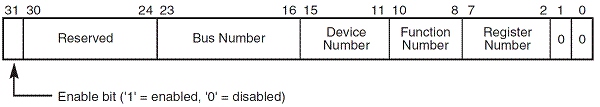
- bit31 是使能对 PCI Bus CONFIG_DATA 的访问;
- bit 30~24 为保留,为只读,访问时返回值为 0;
- bit 23~16 是Bus号;
- bit 15~10 是设备号;
- bit 10~8 是功能号;
- bit 7~2 是配置空间中的寄存器,单位为 DWORD;
- bit 1~0 为只读,读取时放回为0。
直接操作 IO 端口读取 PCI 配置信息分为两步:
- 向 CONFIG_ADDRESS 寄存器写入要读/写的位置;
- 从CONFIG_DATA寄存器(端口0xCFC)读/写所需要数据。
配置空间共 256 字节(地址 0x000xFF), 前 64 字节(地址 0x000x3F )是所有 PCI 设备必须支持的:
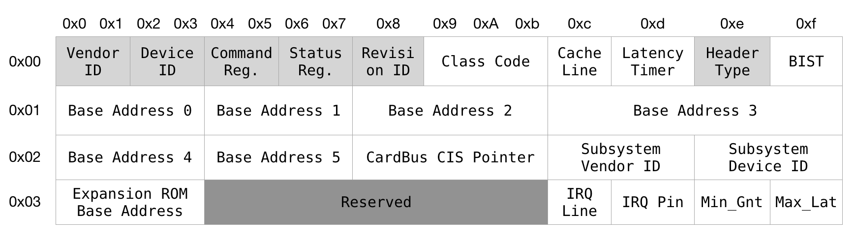
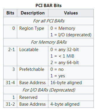
配置空间都是小端存储。Vendor ID 是厂商 ID ,为保证唯一性,需要设备厂商向 PCI SIG 申请获得,Device ID 由厂商自定义。 Base Address Registers (BAR)用来定义该设备占用的 Memory/IO 空间的类型、起始地址和大小,PCI 设备做多有六个 BAR,PCI 桥最多有两个 BAR 。BAR 在 bit0 来表示该设备是映射到 memory 还是 IO,bar 的 bit0 是 readonly 的,也就是说,设备寄存器是映射到 memory 还是 IO 是由设备制造商决定的,其他人无法修改。空间的大小可以用如下方法读取:
- 向寄存器写 0xFFFFFFFF;
- 读出寄存器的值,并取反;
- 再加 1 就是该空间的大小。
下面是 BAR 的结构图:
PCI 枚举是个不断递归调用发现新设备的过程,系统启动时, 从 Host Bridge 开始寻找设备和桥。发现桥后设置 Bus,会发现一个 PCI 设备子树,递归的过程中,BIOS/UEFI (或者 Linux 内核, 如果配置成这样)与每个 PCI 设备进行配置交易, 为其分配安全的地址空间和中断等资源。在整个过程结束后,一颗完整的资源分配完毕的树就建立好了。
PCIe 规范在 PCI 规范的基础上,将配置空间扩展到 4KB。原来的 CF8/CFC 方法仍然可以访问所有PCIe设备配置空间的头255B,但是该方法访问不了剩下的(255-4k)配置空间。
3. Linux #
3.1. user space #
Linux 系统下查询 PCI 设备主要用 lspci 命令和 /sys 文件系统,一个 x86 主机为例:
# lspci
00:00.0 Host bridge: Intel Corporation Device 0958
00:14.0 SD Host controller: Intel Corporation Device 08a7 (rev 10)
00:14.1 Serial controller: Intel Corporation Device 0936 (rev 10)
00:14.2 USB controller: Intel Corporation Device 0939 (rev 10)
00:14.3 USB controller: Intel Corporation Device 0939 (rev 10)
00:14.4 USB controller: Intel Corporation Device 093a (rev 10)
00:14.5 Serial controller: Intel Corporation Device 0936 (rev 10)
00:14.6 Ethernet controller: Intel Corporation Device 0937 (rev 10)
00:14.7 Ethernet controller: Intel Corporation Device 0937 (rev 10)
00:15.0 Serial bus controller [0c80]: Intel Corporation Device 0935 (rev 10)
00:15.1 Serial bus controller [0c80]: Intel Corporation Device 0935 (rev 10)
00:15.2 Serial bus controller [0c80]: Intel Corporation Device 0934 (rev 10)
00:17.0 PCI bridge: Intel Corporation Device 11c3
00:17.1 PCI bridge: Intel Corporation Device 11c4
00:1f.0 ISA bridge: Intel Corporation Device 095e
01:00.0 Network controller: Intel Corporation Centrino Advanced-N 6205 [Taylor Peak] (rev 34)
前面的数字依次是总线号:设备号:功能号,第一个设备就是 Host bridge ,00:1f.0 ISA bridge 是一个 ISA 桥,通过 PCI 扩展了一个 ISA 总线,可以兼容过时的 ISA 总线设备。有个两个 PCI bridge :00:17.0 PCI bridge 和 00:17.1 PCI bridge ,扩展了两条 PCI 总线,也就是说该主机有三条 PCI 总线。而 01:00.0 Network controller 就是 PCI Bus #1 下的一个设备。单独查看该设备的详细信息:
# lspci -s 01:00.0 -vv
01:00.0 Network controller: Intel Corporation Centrino Advanced-N 6205 [Taylor Peak] (rev 34)
        Subsystem: Intel Corporation Centrino Advanced-N 6205 AGN
        Control: I/O- Mem+ BusMaster+ SpecCycle- MemWINV- VGASnoop- ParErr- Stepping- SERR- FastB2B- DisINTx+
        Status: Cap+ 66MHz- UDF- FastB2B- ParErr- DEVSEL=fast >TAbort- <TAbort- <MAbort- >SERR- <PERR- INTx-
        Latency: 0
        Interrupt: pin A routed to IRQ 45      #中断管脚和中断号
        Region 0: Memory at 90000000 (64-bit, non-prefetchable) [size=8K]  #设备占用的地址空间
        Capabilities: [c8] Power Management version 3
                Flags: PMEClk- DSI+ D1- D2- AuxCurrent=0mA PME(D0+,D1-,D2-,D3hot+,D3cold+)
                Status: D0 NoSoftRst- PME-Enable- DSel=0 DScale=0 PME-
        Capabilities: [d0] MSI: Enable+ Count=1/1 Maskable- 64bit+
                Address: 00000000fee0100c  Data: 4191
        Capabilities: [e0] Express (v1) Endpoint, MSI 00
                DevCap: MaxPayload 128 bytes, PhantFunc 0, Latency L0s <512ns, L1 unlimited
                        ExtTag- AttnBtn- AttnInd- PwrInd- RBE+ FLReset+
                DevCtl: Report errors: Correctable- Non-Fatal- Fatal- Unsupported-
                        RlxdOrd+ ExtTag- PhantFunc- AuxPwr- NoSnoop+ FLReset-
                        MaxPayload 128 bytes, MaxReadReq 128 bytes
                DevSta: CorrErr+ UncorrErr- FatalErr- UnsuppReq+ AuxPwr+ TransPend-
                LnkCap: Port #0, Speed 2.5GT/s, Width x1, ASPM L0s L1, Latency L0 <4us, L1 <32us
                        ClockPM+ Surprise- LLActRep- BwNot-
                LnkCtl: ASPM Disabled; RCB 64 bytes Disabled- Retrain- CommClk+
                        ExtSynch- ClockPM- AutWidDis- BWInt- AutBWInt-
                LnkSta: Speed 2.5GT/s, Width x1, TrErr- Train- SlotClk+ DLActive- BWMgmt- ABWMgmt-
        Capabilities: [100 v1] Advanced Error Reporting
                UESta:  DLP- SDES- TLP- FCP- CmpltTO- CmpltAbrt- UnxCmplt- RxOF- MalfTLP- ECRC- UnsupReq- ACSViol-
                UEMsk:  DLP- SDES- TLP- FCP- CmpltTO- CmpltAbrt- UnxCmplt- RxOF- MalfTLP- ECRC- UnsupReq- ACSViol-
                UESvrt: DLP+ SDES- TLP- FCP+ CmpltTO- CmpltAbrt- UnxCmplt- RxOF+ MalfTLP+ ECRC- UnsupReq- ACSViol-
                CESta:  RxErr- BadTLP- BadDLLP- Rollover- Timeout- NonFatalErr+
                CEMsk:  RxErr- BadTLP- BadDLLP- Rollover- Timeout- NonFatalErr+
                AERCap: First Error Pointer: 00, GenCap- CGenEn- ChkCap- ChkEn-
        Capabilities: [140 v1] Device Serial Number 10-0b-a9-ff-ff-b4-93-2c
        Kernel driver in use: iwlwifi   #设备驱动
        Kernel modules: iwlwifi
查看该设备的配置空间:
# lspci -s 01:00.0 -x
01:00.0 Network controller: Intel Corporation Centrino Advanced-N 6205 [Taylor Peak] (rev 34)
00: 86 80 82 00 06 04 10 00 34 00 80 02 00 00 00 00
10: 04 00 00 90 00 00 00 00 00 00 00 00 00 00 00 00
20: 00 00 00 00 00 00 00 00 00 00 00 00 86 80 01 13
30: 00 00 00 00 c8 00 00 00 00 00 00 00 ff 01 00 00
通过 /sys 文件系统可以查看更多信息,/sys/bus/pci/ 目录包含的主要文件:
- devices:目录,包含所有 PCI 设备的文件夹
- drivers :目录,包含所有 PCI 设备所用的驱动
- rescan : 文件,只写,写入一个非零值会导致系统重新扫描所有的 PCI 总线设备
在 /sys/bus/pci/devices 下可以查看所有的 PCI 总线设备:
root@WR-IntelligentDevice:/sys/bus/pci/devices# ls -l
total 0
lrwxrwxrwx 1 root root 0 Nov 26 10:57 0000:00:00.0 -> ../../../devices/pci0000:00/0000:00:00.0
lrwxrwxrwx 1 root root 0 Nov 26 10:57 0000:00:14.0 -> ../../../devices/pci0000:00/0000:00:14.0
lrwxrwxrwx 1 root root 0 Nov 26 10:57 0000:00:14.1 -> ../../../devices/pci0000:00/0000:00:14.1
lrwxrwxrwx 1 root root 0 Nov 26 10:57 0000:00:14.2 -> ../../../devices/pci0000:00/0000:00:14.2
lrwxrwxrwx 1 root root 0 Nov 26 10:57 0000:00:14.3 -> ../../../devices/pci0000:00/0000:00:14.3
lrwxrwxrwx 1 root root 0 Nov 26 10:57 0000:00:14.4 -> ../../../devices/pci0000:00/0000:00:14.4
lrwxrwxrwx 1 root root 0 Nov 26 10:57 0000:00:14.5 -> ../../../devices/pci0000:00/0000:00:14.5
lrwxrwxrwx 1 root root 0 Nov 26 10:57 0000:00:14.6 -> ../../../devices/pci0000:00/0000:00:14.6
lrwxrwxrwx 1 root root 0 Nov 26 10:57 0000:00:14.7 -> ../../../devices/pci0000:00/0000:00:14.7
lrwxrwxrwx 1 root root 0 Nov 26 10:57 0000:00:15.0 -> ../../../devices/pci0000:00/0000:00:15.0
lrwxrwxrwx 1 root root 0 Nov 26 10:57 0000:00:15.1 -> ../../../devices/pci0000:00/0000:00:15.1
lrwxrwxrwx 1 root root 0 Nov 26 10:57 0000:00:15.2 -> ../../../devices/pci0000:00/0000:00:15.2
lrwxrwxrwx 1 root root 0 Nov 26 10:57 0000:00:17.0 -> ../../../devices/pci0000:00/0000:00:17.0
lrwxrwxrwx 1 root root 0 Nov 26 10:57 0000:00:17.1 -> ../../../devices/pci0000:00/0000:00:17.1
lrwxrwxrwx 1 root root 0 Nov 26 10:57 0000:00:1f.0 -> ../../../devices/pci0000:00/0000:00:1f.0
lrwxrwxrwx 1 root root 0 Nov 26 10:57 0000:01:00.0 -> ../../../devices/pci0000:00/0000:00:17.0/0000:01:00.0
目录名称的结构是 PCI 域:总线号:设备号:功能号,PCI 域是 Linux 为了容纳更多总线设备而添加的概念。可以看出 0000:01:00.0 是 0000:00:17.0 PCI 桥扩展的 PCI Bus #1 下的设备,而其他设备都在 Host bridge 下。进入目录 0000:01:00.0,可以看到 sys 文件系统已经把配置空间解析,并分别显示到各个文件中,主要文件的类型和功能:
- class:PCI class (ascii, ro)
- config:PCI 配置空间 (binary, rw),可以用 hexdum 命令查看
- device :PCI device id (ascii, ro)
- vendor:PCI vendor id (ascii, ro)
- enable:设备是否已经使能,1 表示激活,0 表示禁用 (ascii, rw)
- irq:IRQ number (ascii, ro)
- remove:从内核中删除该设备(ascii, wo)
- resource:PCI 设备分配的内存资源 (ascii, ro)
- resource0..N:PCI resource N (binary, mmap, rw[1])
- driver:设备驱动(dir, rw)
我们可以向 0000:01:00.0/remove 文件写 1 ,删除该设备,再向 0000:00:17.0/rescan 写 1 ,重新扫描添加该设备:
/sys/bus/pci/devices# echo 1 > 0000\:01\:00.0/remove
/sys/bus/pci/devices# ls
0000:00:00.0  0000:00:14.2  0000:00:14.5  0000:00:15.0  0000:00:17.0
0000:00:14.0  0000:00:14.3  0000:00:14.6  0000:00:15.1  0000:00:17.1
0000:00:14.1  0000:00:14.4  0000:00:14.7  0000:00:15.2  0000:00:1f.0
/sys/bus/pci/devices# echo 1 > 0000\:00\:17.0/rescan
/sys/bus/pci/devices# ls
0000:00:00.0  0000:00:14.3  0000:00:14.7  0000:00:17.0
0000:00:14.0  0000:00:14.4  0000:00:15.0  0000:00:17.1
0000:00:14.1  0000:00:14.5  0000:00:15.1  0000:00:1f.0
0000:00:14.2  0000:00:14.6  0000:00:15.2  0000:01:00.0
在 driver 目录下访问设备驱动,例如 01:00.0 Network controller 是一个 Wi-Fi 网卡,可以看出它用的驱动是 iwlwifi :
/sys/bus/pci/devices/0000:01:00.0/driver# ls -l
total 0
lrwxrwxrwx 1 root root    0 Nov 29 10:02 0000:01:00.0 -> ../../../../devices/pci0000:00/0000:00:17.0/0000:01:00.0
--w------- 1 root root 4096 Nov 29 10:02 bind
lrwxrwxrwx 1 root root    0 Nov 29 10:02 module -> ../../../../module/iwlwifi
--w------- 1 root root 4096 Nov 29 10:02 new_id
--w------- 1 root root 4096 Nov 29 10:02 remove_id
--w------- 1 root root 4096 Nov 27 12:02 uevent
--w------- 1 root root 4096 Nov 29 10:02 unbind
在 module/parameters 可以读取驱动的各项参数:
/sys/bus/pci/devices/0000:01:00.0/driver/module/parametrs# ls -l
total 0
-r--r--r-- 1 root root 4096 Nov 29 10:03 11n_disable
-r--r--r-- 1 root root 4096 Nov 29 10:03 amsdu_size_8K
-r--r--r-- 1 root root 4096 Nov 29 10:03 antenna_coupling
-r--r--r-- 1 root root 4096 Nov 29 10:03 bt_coex_active
-r--r--r-- 1 root root 4096 Nov 29 10:03 fw_restart
-r--r--r-- 1 root root 4096 Nov 29 10:03 led_mode
-r--r--r-- 1 root root 4096 Nov 29 10:03 nvm_file
-r--r--r-- 1 root root 4096 Nov 29 10:03 power_level
-r--r--r-- 1 root root 4096 Nov 29 10:03 power_save
-r--r--r-- 1 root root 4096 Nov 29 10:03 swcrypto
-r--r--r-- 1 root root 4096 Nov 29 10:03 wd_disable
/sys/bus/pci/devices/0000:01:00.0/driver/module/parametrs# cat 11n_disable
0
3.2. kernel #
Linux 内核通过 CF8/CFC 端口读写 PCI 配置空间,实现函数是 /arch/x86/pci/direct.c 文件的 pci_conf1_read() 和 pci_conf1_write() :
#define PCI_CONF1_ADDRESS(bus, devfn, reg)  (0x80000000 | ((reg & 0xF00) << 16) | (bus << 16) | (devfn << 8) | (reg & 0xFC))

static int pci_conf1_read(unsigned int seg, unsigned int bus, unsigned int devfn, int reg, int len, u32 *value)
{
	unsigned long flags;

	if (seg || (bus > 255) || (devfn > 255) || (reg > 4095)) {
		*value = -1;
		return -EINVAL;
	}

	raw_spin_lock_irqsave(&pci_config_lock, flags);

	outl(PCI_CONF1_ADDRESS(bus, devfn, reg), 0xCF8);

	switch (len) {
	case 1:
		*value = inb(0xCFC + (reg & 3));
		break;
	case 2:
		*value = inw(0xCFC + (reg & 2));
		break;
	case 4:
		*value = inl(0xCFC);
		break;
	}

	raw_spin_unlock_irqrestore(&pci_config_lock, flags);

	return 0;
}

static int pci_conf1_write(unsigned int seg, unsigned int bus, unsigned int devfn, int reg, int len, u32 value)
{
	unsigned long flags;

	if (seg || (bus > 255) || (devfn > 255) || (reg > 4095))
		return -EINVAL;

	raw_spin_lock_irqsave(&pci_config_lock, flags);

	outl(PCI_CONF1_ADDRESS(bus, devfn, reg), 0xCF8);

	switch (len) {
	case 1:
		outb((u8)value, 0xCFC + (reg & 3));
		break;
	case 2:
		outw((u16)value, 0xCFC + (reg & 2));
		break;
	case 4:
		outl((u32)value, 0xCFC);
		break;
	}

	raw_spin_unlock_irqrestore(&pci_config_lock, flags);

	return 0;
}
访问 PCIe 扩展的配置空间需要用 pci_conf2_read() 和 pci_conf2_write() 函数。
4. PCI 设备的枚举过程 #
系统上电后,会采用深度优先算法,从 Host Bridge 开始对所有的 PCI/PCIe 设备进行扫描,其过程简要来说是对每一个可能的分支路径深入到不能再深入为止,而且每个节点只能访问一次。这个过程为 PCI 设备枚举。枚举过程中,系统通过配置读事物包来获取下游设备的信息,通过配置写事物包对下游设备进行设置。以下图为例:
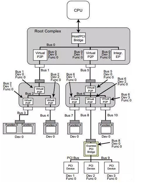
PCI 设备体系是一个树形结构,Host Bridge 扩展的总线为 Bus 0 ,然后从左开始向下搜索,每个 Bridge 扩展一条总线,依次以数字顺序从小到大命名 Bus ID ,向下到尽头后退回。如果去掉了上图的 Bus 3 ,后面设备的 Bus ID 都会发生改变,并向前递进。
在 Linux 系统中,可以用 lspci -t 命令查询系统枚举到的 PCI 设备,结果以树形显示依赖关系,例如:
root@localhost:~# lspci -t -v
-[0000:00]-+-00.0  Intel Corporation Atom Processor Z36xxx/Z37xxx Series SoC Transaction Register
           +-02.0  Intel Corporation Atom Processor Z36xxx/Z37xxx Series Graphics & Display
           +-11.0  Intel Corporation Atom Processor Z36xxx/Z37xxx Series SDIO Controller
           +-12.0  Intel Corporation Atom Processor Z36xxx/Z37xxx Series SDIO Controller
           +-13.0  Intel Corporation Atom Processor E3800 Series SATA AHCI Controller
           +-17.0  Intel Corporation Atom Processor E3800 Series eMMC 4.5 Controller
           +-1a.0  Intel Corporation Atom Processor Z36xxx/Z37xxx Series Trusted Execution Engine
           +-1b.0  Intel Corporation Atom Processor Z36xxx/Z37xxx Series High Definition Audio Controller
           +-1c.0-[01]----00.0  Intel Corporation I210 Gigabit Network Connection
           +-1c.1-[02]----00.0  Intel Corporation I210 Gigabit Network Connection
           +-1c.2-[03]----00.0  Intel Corporation Wireless 3165
           +-1c.3-[04]----00.0  Intel Corporation 82574L Gigabit Network Connection
           +-1d.0  Intel Corporation Atom Processor Z36xxx/Z37xxx Series USB EHCI
           +-1f.0  Intel Corporation Atom Processor Z36xxx/Z37xxx Series Power Control Unit
           \-1f.3  Intel Corporation Atom Processor E3800 Series SMBus Controller
root@localhost:~# lspci
00:00.0 Host bridge: Intel Corporation Atom Processor Z36xxx/Z37xxx Series SoC Transaction Register (rev 11)
00:02.0 VGA compatible controller: Intel Corporation Atom Processor Z36xxx/Z37xxx Series Graphics & Display (rev 11)
00:11.0 SD Host controller: Intel Corporation Atom Processor Z36xxx/Z37xxx Series SDIO Controller (rev 11)
00:12.0 SD Host controller: Intel Corporation Atom Processor Z36xxx/Z37xxx Series SDIO Controller (rev 11)
00:13.0 SATA controller: Intel Corporation Atom Processor E3800 Series SATA AHCI Controller (rev 11)
00:17.0 SD Host controller: Intel Corporation Atom Processor E3800 Series eMMC 4.5 Controller (rev 11)
00:1a.0 Encryption controller: Intel Corporation Atom Processor Z36xxx/Z37xxx Series Trusted Execution Engine (rev 11)
00:1b.0 Audio device: Intel Corporation Atom Processor Z36xxx/Z37xxx Series High Definition Audio Controller (rev 11)
00:1c.0 PCI bridge: Intel Corporation Atom Processor E3800 Series PCI Express Root Port 1 (rev 11)
00:1c.1 PCI bridge: Intel Corporation Atom Processor E3800 Series PCI Express Root Port 2 (rev 11)
00:1c.2 PCI bridge: Intel Corporation Atom Processor E3800 Series PCI Express Root Port 3 (rev 11)
00:1c.3 PCI bridge: Intel Corporation Atom Processor E3800 Series PCI Express Root Port 4 (rev 11)
00:1d.0 USB controller: Intel Corporation Atom Processor Z36xxx/Z37xxx Series USB EHCI (rev 11)
00:1f.0 ISA bridge: Intel Corporation Atom Processor Z36xxx/Z37xxx Series Power Control Unit (rev 11)
00:1f.3 SMBus: Intel Corporation Atom Processor E3800 Series SMBus Controller (rev 11)
01:00.0 Ethernet controller: Intel Corporation I210 Gigabit Network Connection (rev 03)
02:00.0 Ethernet controller: Intel Corporation I210 Gigabit Network Connection (rev 03)
03:00.0 Network controller: Intel Corporation Wireless 3165 (rev 81)
04:00.0 Ethernet controller: Intel Corporation 82574L Gigabit Network Connection
可以看出,Bus 1~Bus 4 是通过 00:1c.0~00:1c.3 四个 Bridge 设备扩展的。